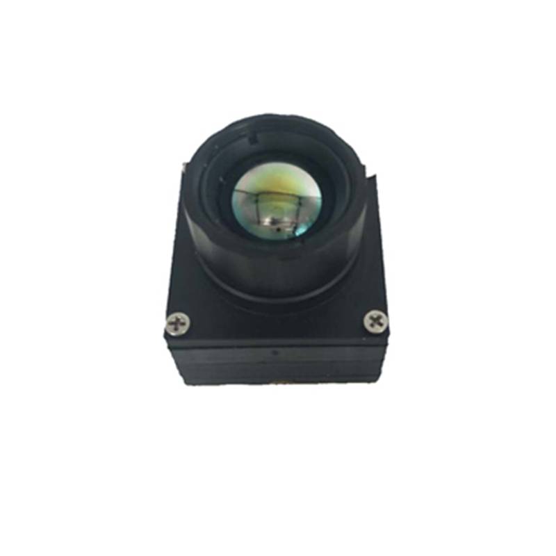
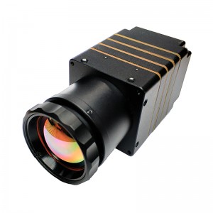
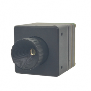
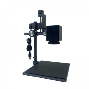
M640 infrared thermal imaging module
1 Product Features
1. The product is small in size and easy to integrate;
2. FPC interface is adopted, which is rich in interfaces and easy to connect with other platforms;
3. Low power consumption;
4. High image quality;
5. Accurate temperature measurement;
6. standard data interface, support secondary development, easy integration, support access to a variety of intelligent processing platform.
♦ Product parameters
|
Type |
M640 |
|
Resolution |
640×480 |
|
Pixel space |
17μm |
|
|
55.7°×41.6°/6.8mm |
|
FOV/Focal length |
|
|
|
28.4°x21.4°/13mm |
* Paralles interface in 25Hz output mode;
|
FPS |
25Hz | |
|
NETD |
≤60mK@f#1.0 | |
|
Working temperature |
-15℃~+60℃ | |
|
DC |
3.8V-5.5V DC | |
|
Power |
<300mW* | |
|
Weight |
<30g(13mm lens) |
|
|
Dimension(mm) |
26*26*26.4(13mm lens) |
|
|
Data interface |
parallel/USB | |
|
Control interface |
SPI/I2C/USB | |
|
Image intensification |
Multi-gear detail enhancement | |
|
Image calibration |
The shutter correction | |
|
Palette |
White glow/black hot/multiple pseudo-color plates |
|
|
Measuring range |
-20℃~+120℃(customized up to 550℃) |
|
|
Accuracy |
±3℃ or ±3% |
|
|
Temperature correction |
Manual /Automatic | |
|
Temperature statistics output |
Real-time parallel output | |
|
Temperature measurement statistics |
Support maximum /minimum statistics,temperature analysis |
|
Infrared thermal imaging breaks through the visual barriers of natural physics and common things, and upgrades the visualization of things. It is a modern high-tech science and technology, which plays a positive and important role in the application of military activities, industrial production and other fields. It is a kind of equipment which uses infrared thermal imaging technology to transform the temperature distribution image of the object into visual image by detecting the infrared radiation of the object, signal processing, photoelectric conversion and other means.
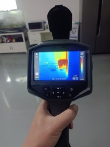
This infrared thermal imaging design has developed from a bulky machine into a portable device for field test, which is easy to carry and collect. Fully considering the user's needs and environmental factors, the model is intuitive and concise, with business black as the main color and eye-catching yellow as the embellishment. It not only gives people the aesthetic feeling of high-end science and technology, but also highlights the strong and durable quality of the equipment, which is in line with the industry attribute of the equipment. Industrial grade three proofing design, exquisite surface treatment process, with good waterproof, dustproof, shockproof performance, suitable for all kinds of harsh industrial environment. The overall design is in line with ergonomics, intuitive man-machine interface, good hand-held grip, anti drop, passive non-contact detection and identification, more safe and simple operation.
In practical application, the hand-held infrared thermal imager is mainly used for industrial troubleshooting, which can quickly detect the temperature of the processing parts, so as to grasp the necessary information, and can quickly diagnose the faults of electronic devices such as motors and transistors. It can also be used to detect the bad contact with electrical equipment, as well as overheated mechanical parts, so as to prevent serious fires and accidents Accidents provide detection means and diagnostic tools for industrial production and many other aspects.
Infrared thermal imaging equipment can also be used as an effective fire alarm equipment. We know that in a large area of forest, hidden fires are often unable to be accurately judged by UAVs. Thermal imager can quickly and effectively detect these hidden fires, accurately determine the location and scope of the fire, and find the ignition point through smoke, so as to prevent and extinguish them as early as possible.
user interface description

Figure1 user interface
The product adopts 0.3Pitch 33Pin FPC connector (X03A10H33G), and the input voltage is:3.8-5.5VDC, undervoltage protection is not supported.
Form 1 interface pin of thermal imager
| Pin number | name | type |
Voltage |
Specification | |
| 1,2 | VCC | Power | -- | Power supply | |
| 3,4,12 | GND | Power | -- | 地 | |
| 5 |
USB_DM |
I/O | -- |
USB 2.0 |
DM |
| 6 |
USB_DP |
I/O | -- | DP | |
| 7 |
USBEN* |
I | -- | USB enabled | |
| 8 |
SPI_SCK |
I |
Default:1.8V LVCMOS ; (if need 3.3V LVCOMS output, please contact us) |
SPI |
SCK |
| 9 |
SPI_SDO |
O | SDO | ||
| 10 |
SPI_SDI |
I | SDI | ||
| 11 |
SPI_SS |
I | SS | ||
| 13 |
DV_CLK |
O |
VIDEOl |
CLK | |
| 14 |
DV_VS |
O | VS | ||
| 15 |
DV_HS |
O | HS | ||
| 16 |
DV_D0 |
O | DATA0 | ||
| 17 |
DV_D1 |
O | DATA1 | ||
| 18 |
DV_D2 |
O | DATA2 | ||
| 19 |
DV_D3 |
O | DATA3 | ||
| 20 |
DV_D4 |
O | DATA4 | ||
| 21 |
DV_D5 |
O | DATA5 | ||
| 22 |
DV_D6 |
O | DATA6 | ||
| 23 |
DV_D7 |
O | DATA7 | ||
| 24 |
DV_D8 |
O |
DATA8 |
||
| 25 |
DV_D9 |
O |
DATA9 |
||
| 26 |
DV_D10 |
O |
DATA10 |
||
| 27 |
DV_D11 |
O |
DATA11 |
||
| 28 |
DV_D12 |
O |
DATA12 |
||
| 29 |
DV_D13 |
O |
DATA13 |
||
| 30 |
DV_D14 |
O |
DATA14 |
||
| 31 |
DV_D15 |
O |
DATA15 |
||
| 32 |
I2C_SCL |
I | SCL | ||
| 33 |
I2C_SDA |
I/O |
SDA |
||
communication adopts UVC communication protocol, image format is YUV422, if you need USB communication development kit, please contact us;
in PCB design, parallel digital video signal suggested 50 Ω impedance control.
Form 2 Electrical specification
Format VIN =4V, TA = 25°C
| Parameter | Identify |
Test condition |
MIN TYP MAX |
Unit |
| Input voltage range | VIN | -- |
3.8 4 5.5 |
V |
| Capacity | ILOAD | USBEN=GND |
75 300 |
mA |
| USBEN=HIGH |
110 340 |
mA | ||
|
USB enabled control |
USBEN-LOW | -- |
0.4 |
V |
| USBEN- HIGN | -- |
1.4 5.5V |
V |
Form 3 Absolute Maximum rating
| Parameter | Range |
| VIN to GND | -0.3V to +6V |
| DP,DM to GND | -0.3V to +6V |
| USBEN to GND | -0.3V to 10V |
| SPI to GND | -0.3V to +3.3V |
| VIDEO to GND | -0.3V to +3.3V |
| I2C to GND | -0.3V to +3.3V |
|
Storage temperature |
−55°C to +120°C |
| Operating temperature | −40°C to +85°C |
Note: Ranges listed that meet or exceed absolute maximum ratings may cause permanent damage to the product.This is just a stress rating;Don't mean that the functional operation of the Product under these or any other conditions is higher than those described in the operations section of this specification. Prolonged operations that exceed maximum working conditions may affect the reliability of the product.
Digital interface output sequence diagram(T5)
M640
Attention
(1) It is recommended to use Clock rising edge sampling for data;
(2) Field synchronization and line synchronization are both highly effective;
(3) The image data format is YUV422, the data low bit is Y, and the high bit is U/V;
(4) The temperature data unit is (Kelvin (K) *10), and the actual temperature is read value /10-273.15 (℃).
Caution
To protect you and others from injury or to protect your device from damage, please read all of the following information before using your device.
1. Do not look directly at the high-intensity radiation sources such as the sun for the movement components;
2. Do not touch or use other objects to collide with the detector window;
3. Do not touch the equipment and cables with wet hands;
4. Do not bend or damage the connecting cables;
5. Do not scrub your equipment with diluents;
6. Do not unplug or plug other cables without disconnecting the power supply;
7. Do not connect the attached cable incorrectly to avoid damaging the equipment;
8. Please pay attention to prevent static electricity;
9. Please do not disassemble the equipment. If there is any fault, please contact our company for professional maintenance.
picture view
The shutter correction function can correct the non-uniformity of infrared image and the accuracy of temperature measurement.It takes 5-10min for the equipment to be stable during startup.The device starts the shutter by default and corrects for 3 times. After that, it defaults to no correction. The rear end can call the shutter regularly to correct the image and temperature data.


